The Astronomical Observatory
The building construction
The main building of the New Millennium Observatory is a typical Italian house.
The construction began on 20th March 1998.
In the following images on the right you can see the build-up phases from the bottom of the building to the roof.
Some technical features are visible: from the big excavator to the strong iron armature of the basement walls.
The building is developed on three levels: the bottom one is a garage and a meeting room, the middle level is the living apartment, and the top one is the observatory, with the dome, the control room, a little bedroom and services.
My brother Luca, an all range engineer, with a lot of skills for any kind of work, done all the project of the structure.

The grass-field of the observatory on March 20, 1998, the day I started the costruction of the observatory. |

A big excavator. |

Excavator work is finished. |
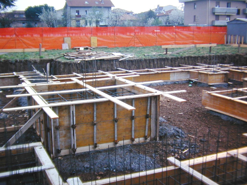
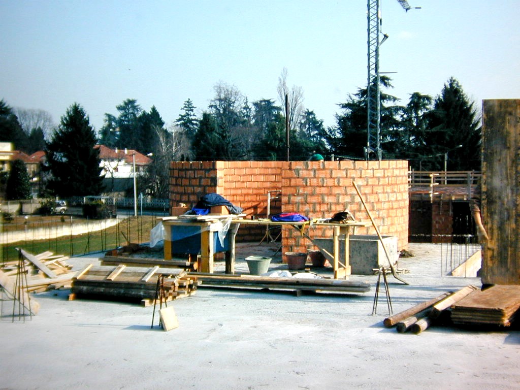
Some pre-structural work |

Concrete and iron for the telescope basement. |
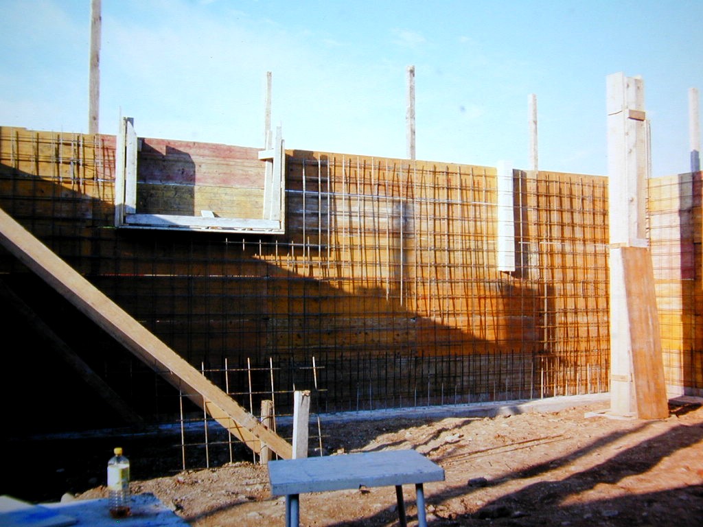
Work in progress. |

Work in progress. |
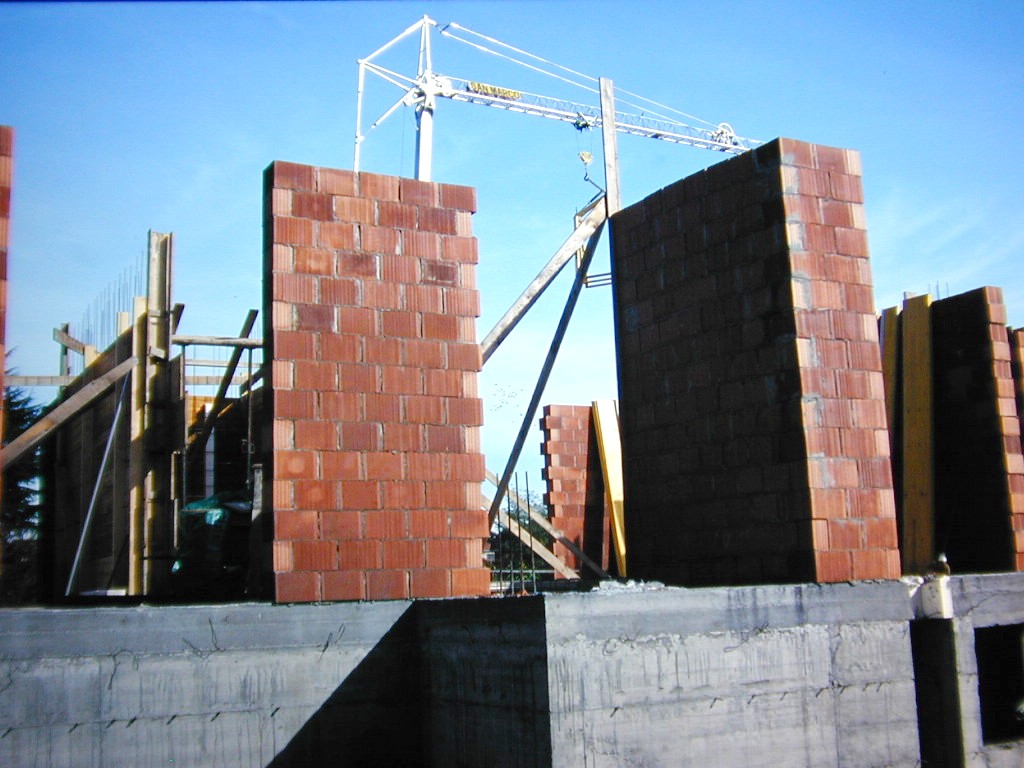
Work in progress. |

Concrete for the basement of the dome wall. |
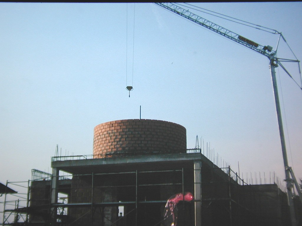
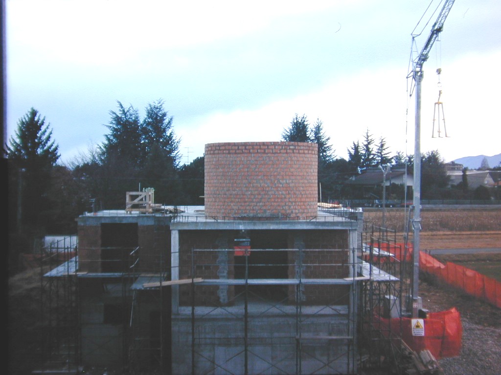
The dome structure is growing. |

The dome structure is growing. |
The dome structure is growing. |
The top-roof of the observatory. |
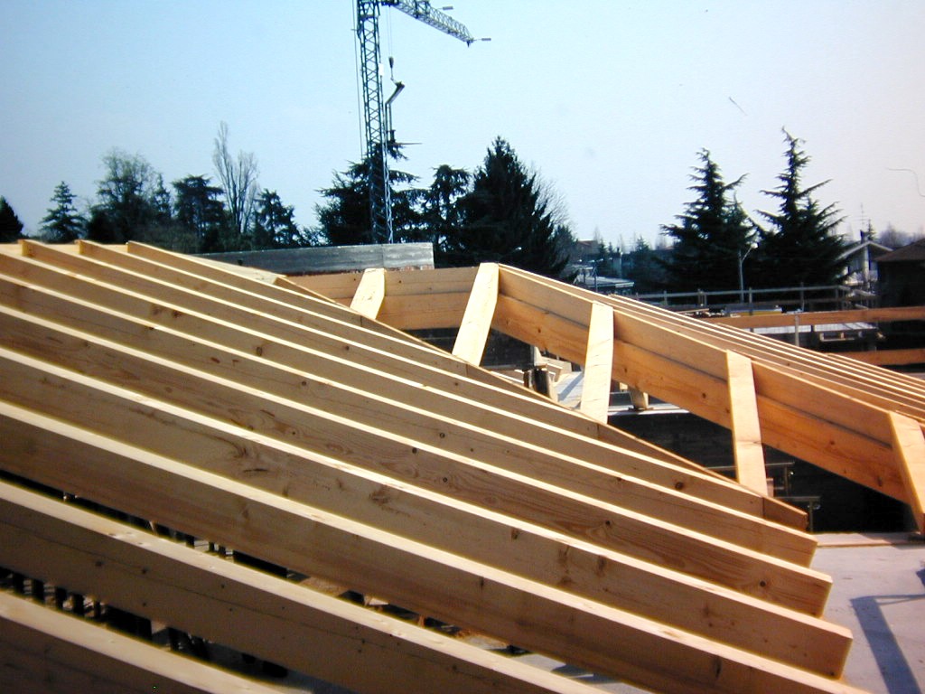
The top-roof of the observatory. |
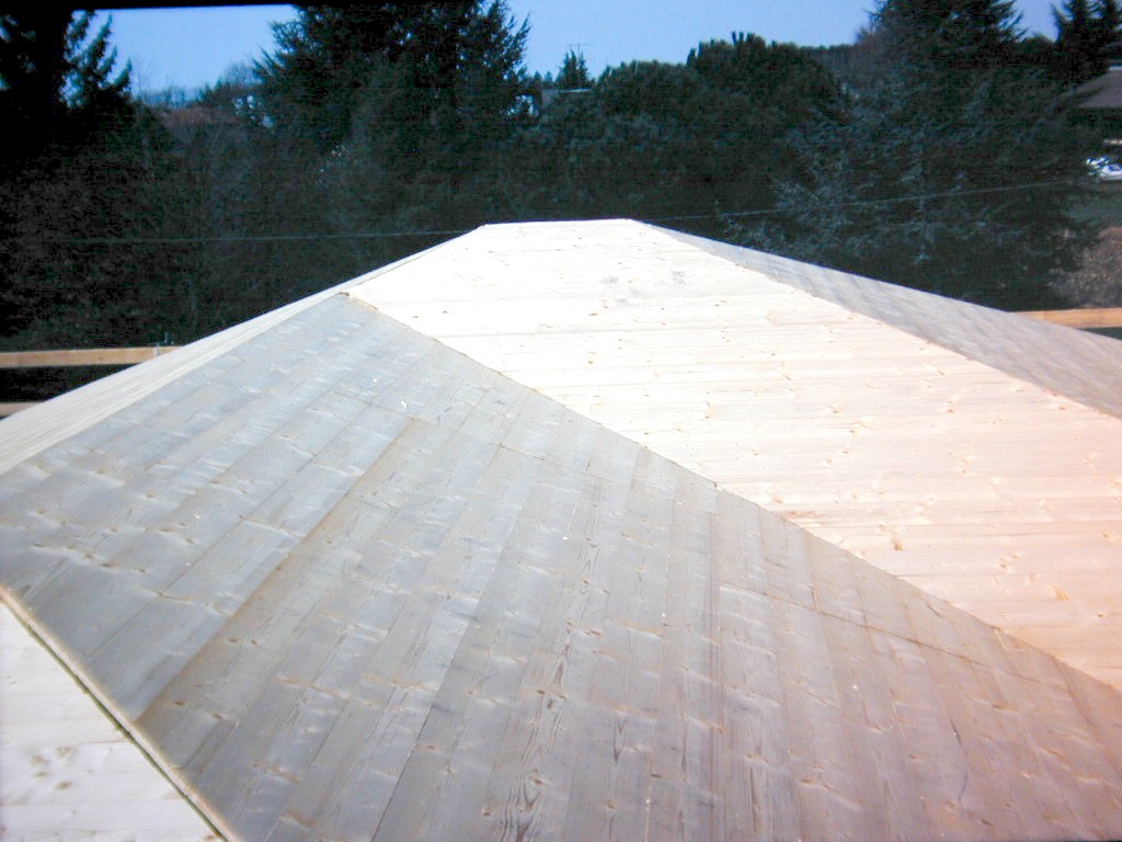
The top-roof of the observatory. |
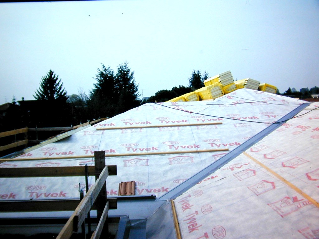
The top-roof of the observatory. |

The dome structure is growing. |

The walls of the dome just before to install the aluminium structure. |
The dome construction
|
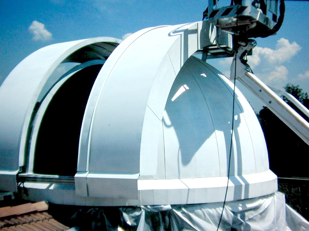
This is one of the principal features of the whole observatory. A dome is more expensive than a roll-off roof and in Italy there are not many dome-makers, and these domes are very expensive, so, after many month of thinking I decided to do-it-by-myself! I spent a lot of time to set-up the project developing all the drawings in AutoCAD. At the beginning with a no-dimension structure, than with the big help of my brother, we make software simulation of the structure to get a self-sustaining dome as light as possible but strong enough to resists to wind gust (fortunately not so strong in Mozzate) and to a little amount of snow (in the last Century the heaviest snow was about 80cm). After a series of simulation we obtained the best solution for the structure. Than, I draw each part in AutoCAD so that, after the calendering of the aluminium profiles we cut them at the exact measure. After that, a local mechanical industry welded all the parts together. Then, always with the help of my brother, we put the aluminium coils on each of the 32 slices of the dome. Every joint was sealed with special silicon for aluminium. In summer 2001 the dome was painted with aluminium car paint. Following this I put all around the door a special PVC tissue to prevent water incoming during thunderstorms with strong wind. In the following fall, the dome was insulated with a 32-mm thick sheet of Eurobatex, an elastomeric rubber foam produced in Italy by Union Foam used for the thermal insulation of refrigeration, air conditioning and heating systems. Finally the inner side of the done has been covered with a thin marine plywood sheet with synthetic coating. This results are visible in the latest snapshots. After more than ten years of weather exposition I never observe some flood of water inside the dome. Only, in the first periods we get some drops coming from the hole of the rivets but this problem was solved rather quickly with acrylic paint dropped in these little holes. In Spring 2011 due to problems of peeling of the paint, the dome was stripped and repainted with water-based enamel. Technical data of the domeThe diameter of the dome is 4.2 m and the aperture is 1.4 m wide. The angle of the sky covered in altitude is 105 degree so it is always possible to look at the zenith and to follow the object well behind. The dome is totally in aluminium and stainless steel so there is no risk of corrosion neither for oxidation nor for galvanic corrosion. The circular rail is in stainless steel and the main 6 wheels are for high-speed precision machinery so the smoothness of the rotation is very good. The total weight, at the present, is around 600 kg, but you can rotate the dome with only one finger. For technical information, a force of 120N is needed to start the rotation and only 80 N are required to keep rotation at speed of 4 degree per second. |
The skeleton of the dome. All aluminium. |
An aerial view of the dome under construction. |

The skeleton of the dome. |
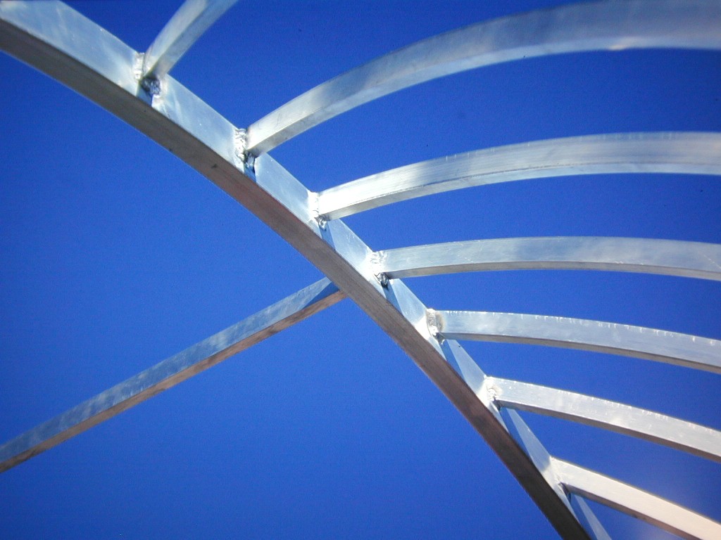
A close-up of the structure. |

The skeleton viewed from inside the dome. |

One of the six wheels that support the dome. |
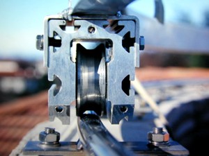
The wheel has a conical section that rolls on a stailess-steel cylindrical rail. |

The dome covered with aluminium sheets. |

External view. |

Inside the dome. |

A view through-out the door. |
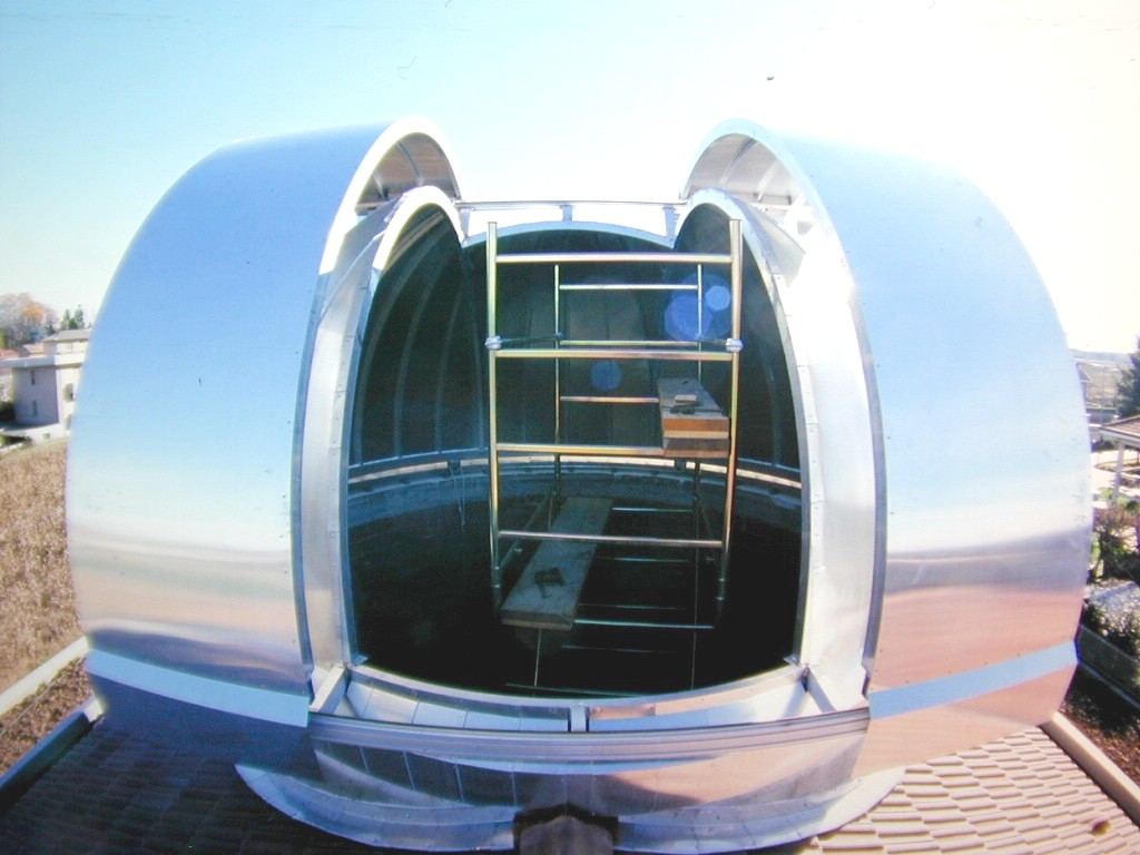
A fish-eye view of the door. |

Painting the dome... |
Painting the dome... |
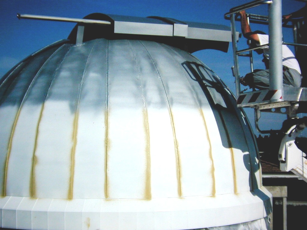
Painting the dome... |

Dome painted! |

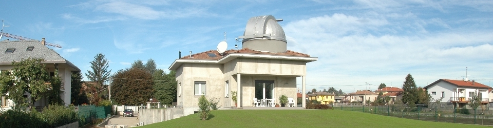
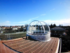
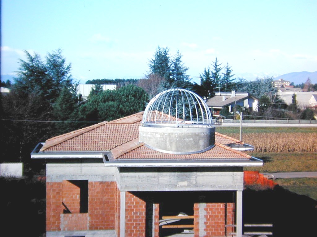
Esternal view of the building with finished dome. |
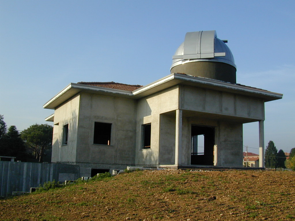
Esternal view of the building with finished dome. |
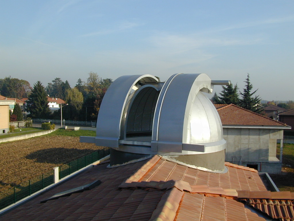
Esternal view of the building with finished dome. |
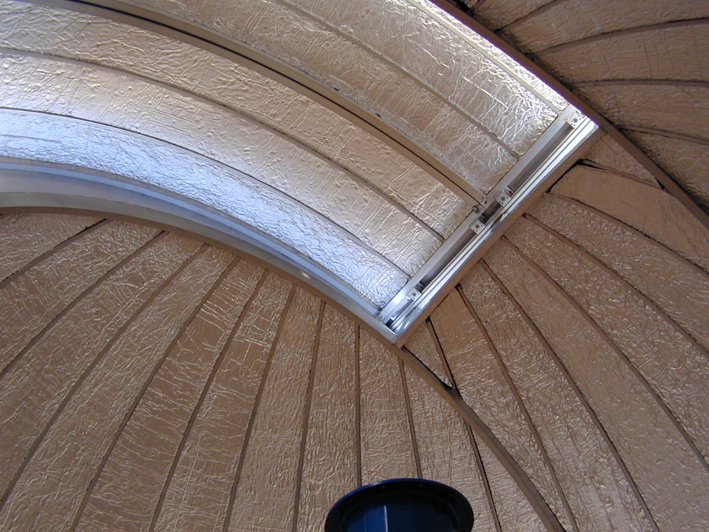
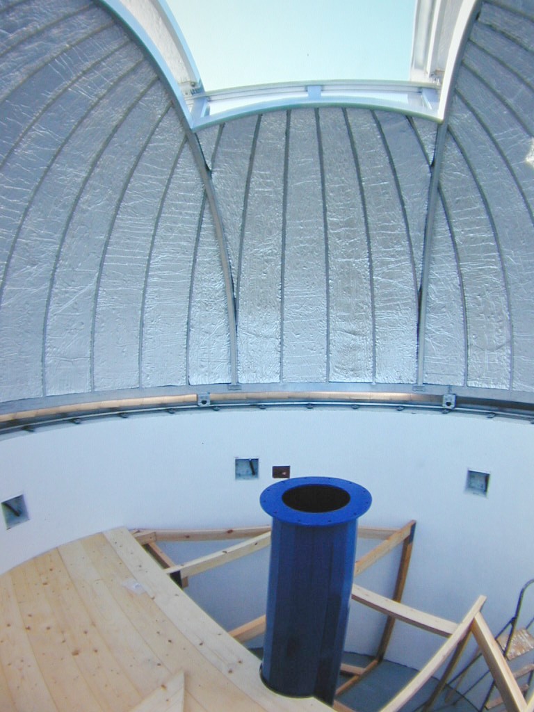
Insulation of the dome. |
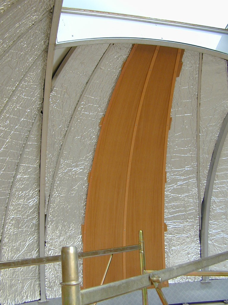
Internal finishing with marine plywood. |

Internal finishing with marine plywood. |
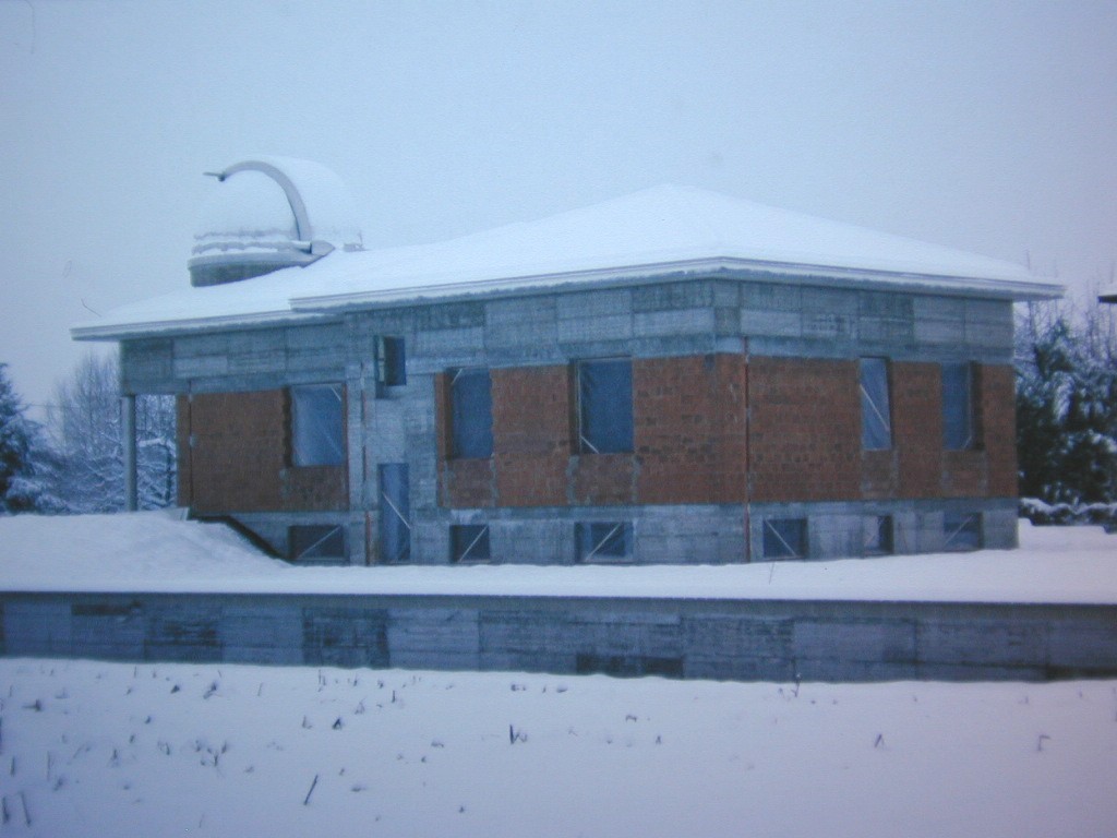
Under the snow. |
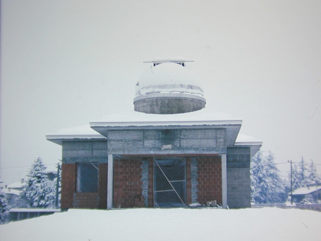
Under the snow. |
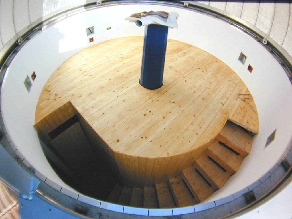
Dome floor and telescope pier
|
At the center of the dome was placed the support pier of the telescope. Approximately 3 meters high, it has a conical section, with thickness of 10mm. Its inside was filled with lightweight concrete to increase the flexural rigidity. To dampen vibrations, between the column and the base was placed a special anti-vibration mat paragraph, typically used for machine tools. Around the column was built a wooden structure that allows to have the floor of the dome completely separate from the telescope. |
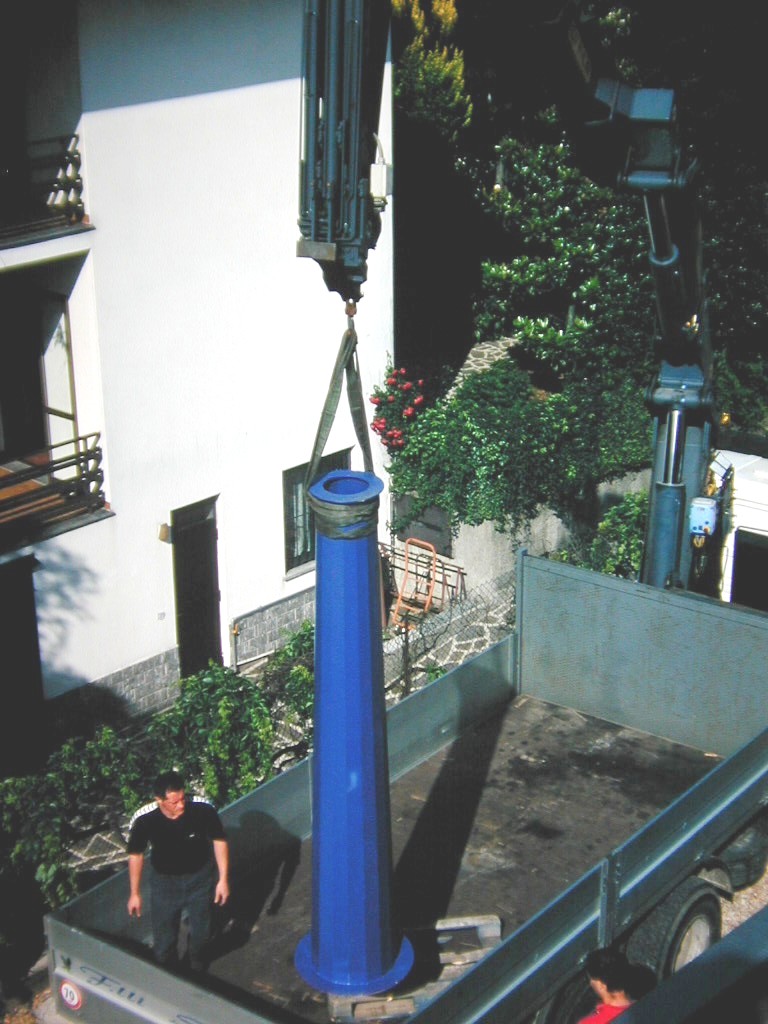
Installation of the telescope pier. |

Installation of the telescope pier. |

Installation of the telescope pier. |
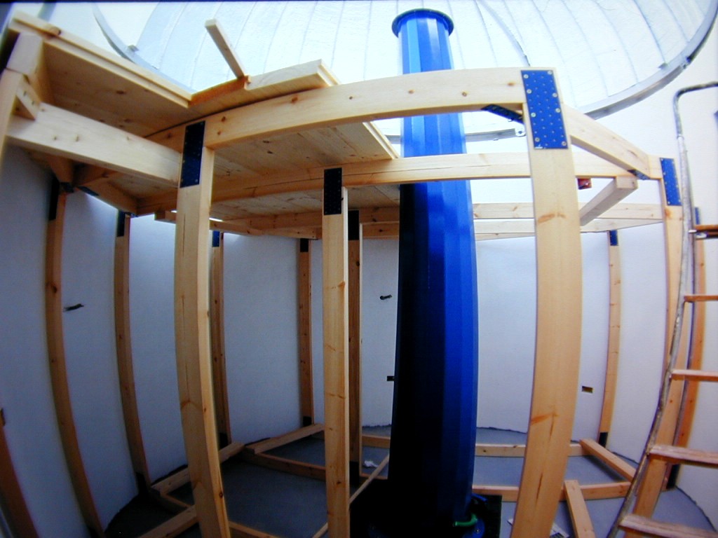
The support lactice of the internal roof. |
The support lactice of the internal roof. |

Intenal roof. |
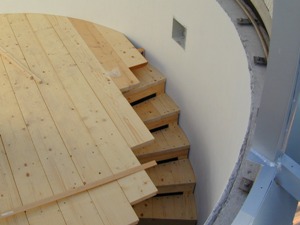
Also the access ladder is made of wood. |
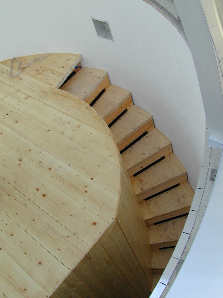
Also the access ladder is made of wood. |
Fish-eye view of the internal. |
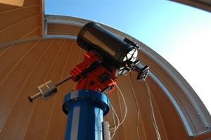
Telescope: ParamoutME with C14 and U47 |
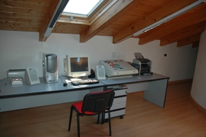
Control room. |

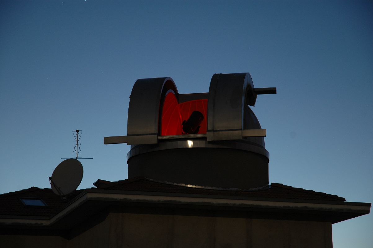
Observatory on October 29th, 2006. |
Dome rotation and automation
|
The rotation of the dome is provided by two electric motors which transmit the movement through a wheel friction by Angst+Pfister. The wheels are pressed against the rim of the dome by a gas spring with a force of 200N each. The motors are three-phase and are managed by a 220V inverter which is also able to manage the return signal from a position encoder. Finally, a dedicated software written by me, keeps aligned the opening of the dome with the pointing direction of the telescope. In this regard, I recommend reading the page abou AutoDome software. |

One of the two rotation motors. |
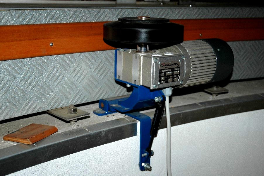
Motor, friction wheel and gas spring. |

Motor, friction wheel and gas spring. |

Technical data of the motor. |

Technical data of the motor. |

Temporary installation of the encoder. |